TL;DR: Reolink seems to use T568B except grey goes to blue, and purple goes to brown-white. Link to heading
Recently, one of the cameras I had set up at a family member’s house started regularly losing connectivity. Link to heading
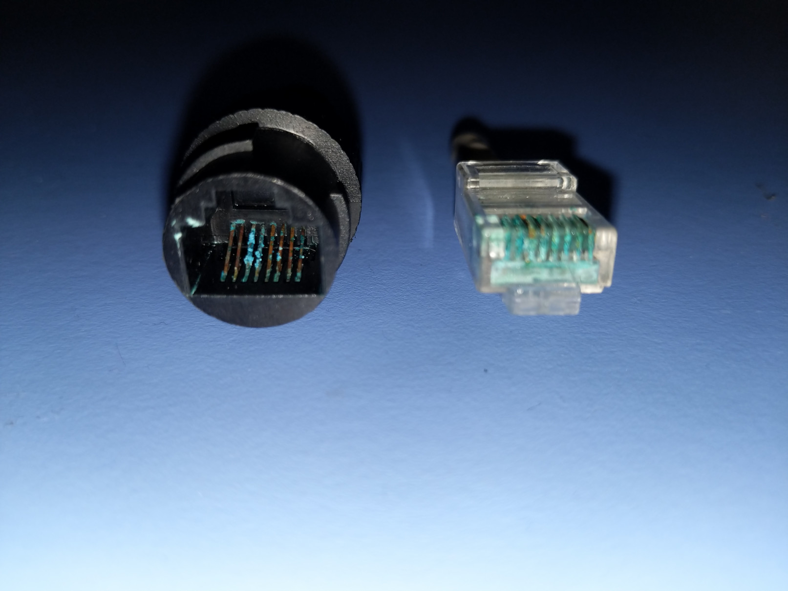
There are some things in life that are better wet than dry; electrical connections are not among them. Without proper weatherproofing around the junction point on the wiring (most kits include a cover for this) the RJ45 jack on the camera had turned green with corrosion.
I’m very much of the philosophy that repairing things is preferable to replacing them (when it’s practical) and because I’m also sometimes kind of cheap, I decided to try and repair the camera.
This is not what you want your connectors looking like:

I had previously checked the Reolink website at some point and vaguely recalled a document covering whether they used the T568A or TB68B standard. But when I tried to find the link, I found a 404 error and sadly accepted that the page I’d looked at before had been taken down. With the Wayback Machine being down this week, I couldn’t find an archived copy of that page and needed some other way to confirm the wiring layout.
I figured that I had a 50/50 chance of getting it right (either T56A or T568B) and since Cat5 connectors are much cheaper than security cameras, I thought I’d give it a shot.
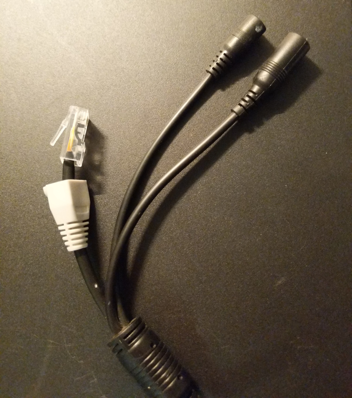
But when I cut off the end of the cable, I discovered something unexpected: only 6 (rather than 8) wires, 2 of which were non-standard colors: grey and blue. (Regretfully, I didn’t take a picture of this, but trust me you aren’t missing out on much.)
The good news is that with a bit of searching the internet I was able to find the information and I needed, and thanks to a helpful youtuber I was able to observe video proof of a functioning wiring layout.
While most of the repairs I’ve seen online use a female (punchdown) replacement, that to me seemed like it would be difficult to waterproof, so I grabbed my trusty Klein Tools crimper and put another male end on instead. It was a bit tricky to get the wires into the correct positions given that there were only 6 out of 8 of them, but after a bit of wiggling around (and losing count of how many times I removed and re-inserted the wires), this technological intercourse reached a successful climax and I got the job done.
Please don’t tell my electrician friends that I put this mod plug end on like this. Pretend you never saw the boot, either.

After replacing the patch cable (this household had many to spare) I plugged everything in and created a connection that was much better than any I’ve ever found on Tinder.
And as a bonus, since I’d recently installed a Power-Over-Ethernet switch at this location, the camera now runs on PoE instead of the supplied barrel-jack 12V AC adapter.